Discord Music Bot
Discord is a popular online communication platform with text and voice chat features. One reason for Discord's popularity is its extensive support for developers, including streamlined application creation wizards, clearly communicated permissions, and a simple API with detailed documentation. A popular Discord application is a music bot which can stream the audio from any public Youtube video into the user's voice channel. This allows for people to be able to listen to music together while having a conversation. Unfortunately, some of the larger music bots which operated on freemium models have been issued cease and desist orders for modifying Youtube's service for commercial use. This inspired me to create my own Discord music bot just for Discord servers that I'm in.
I wrote this music bot in Python using a Python API wrapper from Github user Rapptz called discord.py. The bot is capable of enqueuing youtube videos either through search terms or direct link, allows for entire playlists to be enqueued in one command, has standard stop, pause, and resume commands, and supports skipping songs, viewing what songs are left in the queue, removing songs from the queue, and shuffling either the whole queue or a contiguous subsection of the queue. The bot works by waiting for a command to be given in one of the text channels then parses the command and its arguments to determine which operation to perform. Music is played through ffmpeg using the Discord API. Each server's music queue is a custom queue implementation which allows for extra functionality. The source code for this bot can be found on my Github profile.
I am still occasionally updating this bot and adding features. In the future I plan on adding non-music functionality. It is currently running on an AWS EC2 instance, but I have not made the invite link public.
Qi Wireless Charger
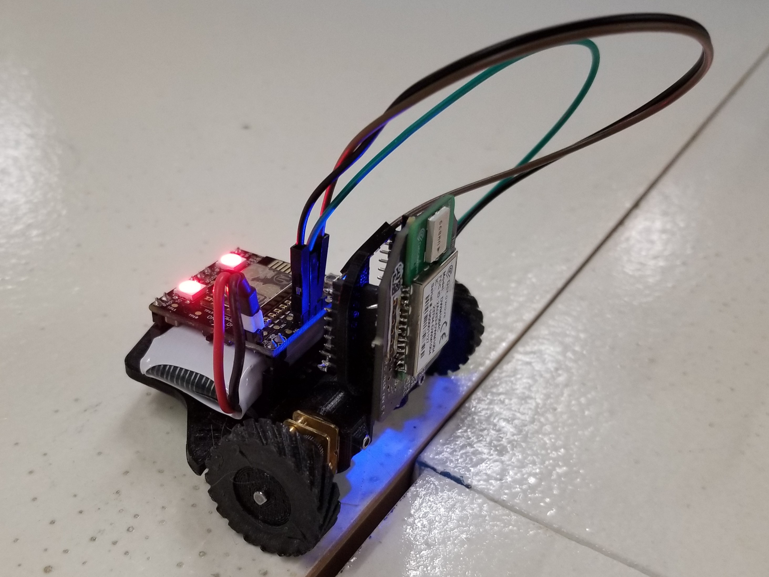
For my senior design class (three quarter-term series) at Oregon State University, I worked in a team of four on a project entitled "Power Management for Collective Ground Robots." The team consisted of two electrical and computer engineering students, Thomas Snyder and me, as well two computer science students, Eric Prather and Miguel Ruiz . We worked alongside the Human-Machine Teaming laboratory (HMTLab) under Dr. Julie Adams to design, implement, and test a power management system for unmanned ground vehicles (UGVs). These UGVs operate in a "swarm" inspired by natural swarming animals such as birds and bees. This means that each robot should be able to make decisions based on data it can observe such as location, obstacles, or targets as well as data collected from nearby robots in the swarm, rather than receiving instructions from a centralized server. The effects of operating robots under this decentralized paradigm is the focus of the swarm robotics research.
Our task was to develop both hardware and software to facilitate battery status and charging tasks. These include determining when the UGV needs to charge and installing hardware which allows the battery to be charged without precise or human-aided positioning. The members of my team who studied computer science programmed the algorithms which determines when the robot needs to charge as well as an optional client-server system which allows for monitoring of collected robot data, which is expandable for a swarm of up to 100 robots. The hardware designed for this project includes a sensor processing board which allows for essential functionality and a wireless charging dock which robots could back into to refill their batteries.
I designed the wireless charging dock for this project. The charging system had a couple main goals. First, due to some limitations of the accuracy of the sensors on the UGVs, it was desirable to have a larger range for the UGVs to be able to charge within than a standard single-coil charging pad. Another important aspect is that since there can potentially be up to 100 UGVs in the swarm (potentially more once expanded), the charging system should support charging up to 10 UGVs at once. To address each of these goals, I partitioned the charging system into two modules: one module manages a single charging station, while the other module provides power to up to 10 charging station modules.
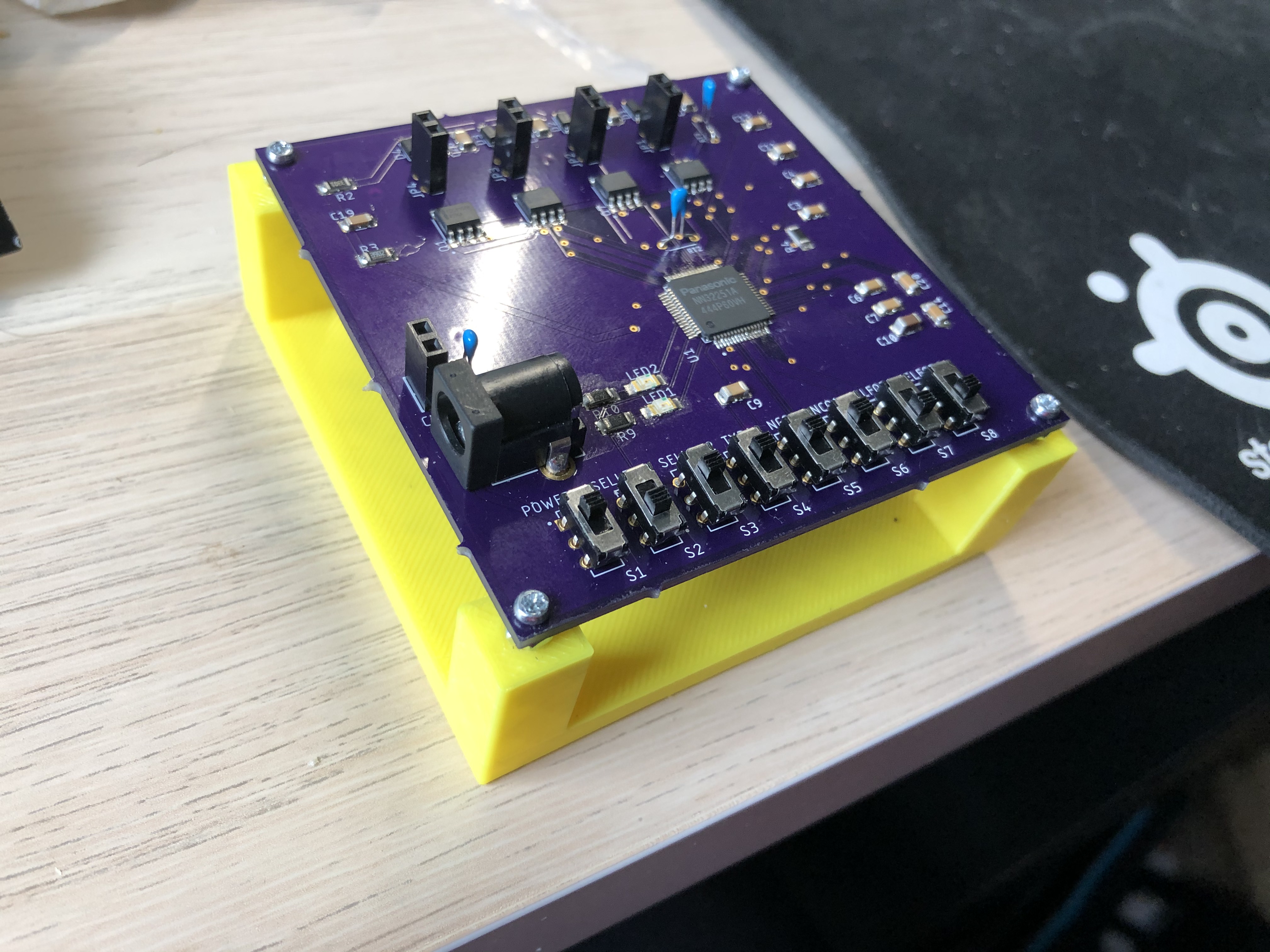
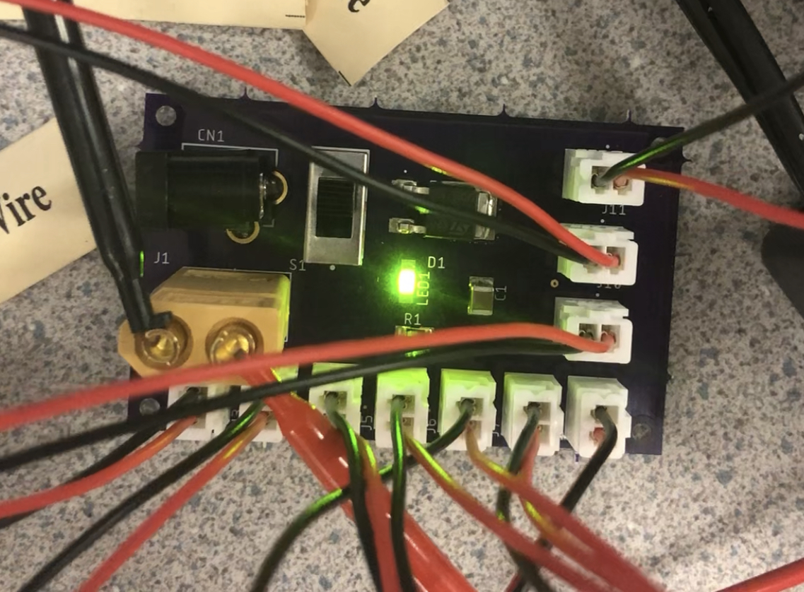
The wireless charging board utilizes a Qi-compliant wireless transmitter integrated circuit which allows for free positioning along a coil array. This means that when a Qi-compliant receiver coil is positioned anywhere along the coil array, the appropriate transmitter coil will begin to tranfer energy. The board that I designed has a few switches which change the settings of the integrated circuit, including the number of coils that the charging station has (up to 4). The power distribution board is much simpler. It consists of a power switch, an indicator LED, a diode to prevent reverse current, and a capacitor to stabilize the voltage. Other than that, it provides power to each of the 10 wireless charging boards.
2-Axis Robotic Arm
The 2-axis robotic arm was for my junior design class, which was a two quarter-term class intended to prepare students for senior design and future design work. Unlike senior design, the project didn't have a client other than the instructor. There were a few constraints and requirements that we were given for the project, but we also chose an additional requirement that added a computer vision feature. This project was designed and implemented by Thomas Snyder , Tristan Thompson , and myself.
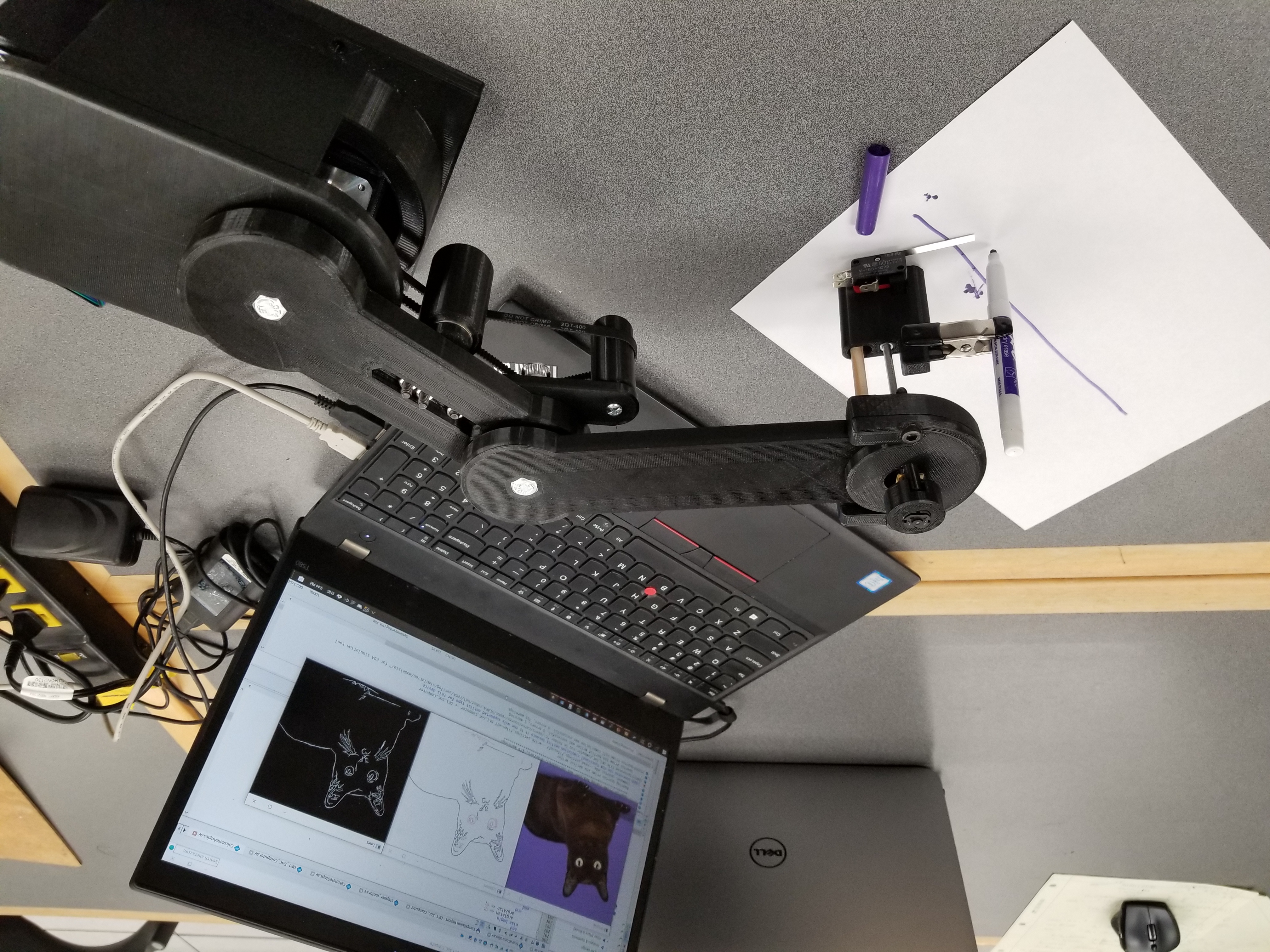
The goal of this project was to create a robotic arm of type SCARA (Selective Compliance Articulated Robot Arm) to be able to draw arbitrary shapes and illustrations. We also included a feature where an image could be given to the system or captured via a webcam and the instructions to replicate the image could be generated and fed to the robot arm using standard G-code commands. For this project, we were able to borrow a SoC FPGA (system on a chip field programmable gate array), and we tried to maximize our usage of it. The flow of data is shown below.
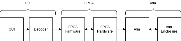
The user can upload images or capture an image from their device's webcam using the GUI (graphical user interface). This image is fed through some computer vision models using color edge detection, which generates G-code instructions based on the contours mapped from the image. Alternatively, the user can upload a G-code file. The G-code is transmitted through a serial port to the ARM processor included in the SoC FPGA. The ARM processor parses the G-code commands. The FPGA itself is used to compute the inverse kinematics required to translate the cartesian coordinates into the angles to which each axis of the arm should rotate. This is converted into a certain number of steps to which the stepper motors controlling the arm should adjust. The FPGA sends pulses to separate stepper motor driver hardware through the GPIO (general purpose input/output) pins, which in turn change the rotation of the stepper motors.
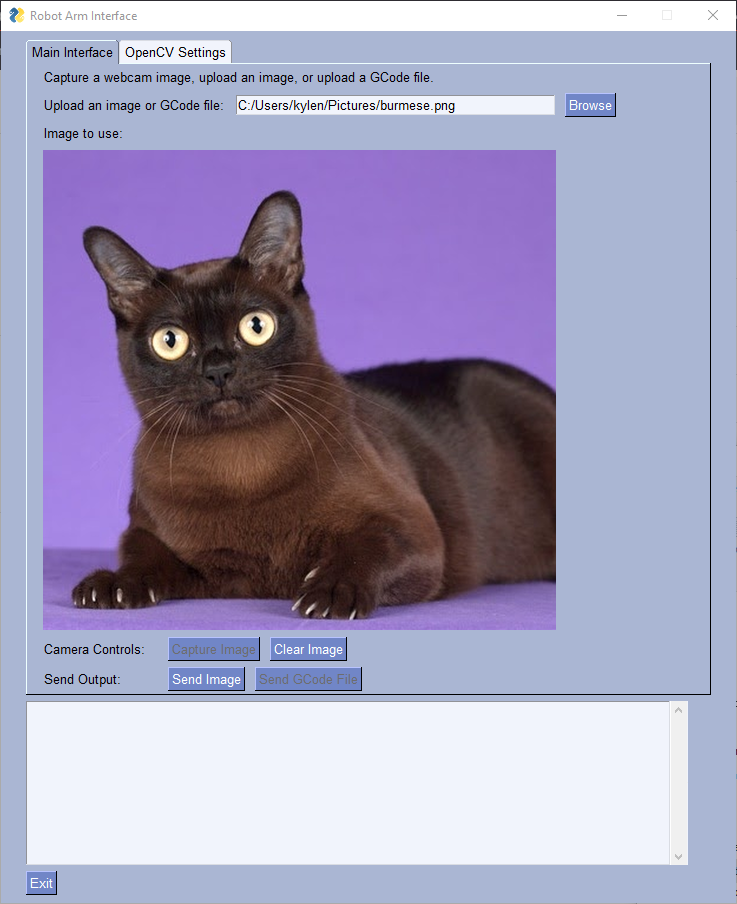
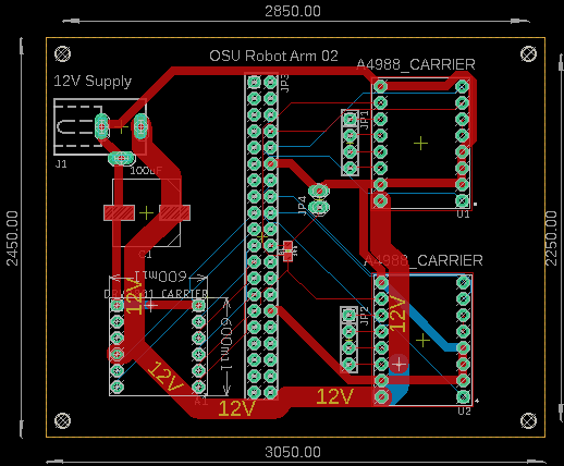
I personally worked on the GUI, the stepper motor control HDL (Hardware Description Language), and a PCB to hold motor drivers and organize connections. The GUI was written in Python using PySimpleGUI. It allows users to upload images, upload G-code files, capture images using their computer's webcam (when available), and set settings for OpenCV. The output box is used to provide operating information to the user, such as instructing the user to switch to a certain color writing utensil.
The stepper motor control HDL contains a SystemVerilog module which takes in an 8-bit integer, direction bit, and start signal. When start is asserted, pulses are sent to stepper motor drivers, and it counts the pulses until the desired number of steps is reached. The GPIO pins from the FPGA are connected to the stepper motor driver modules through the PCB. There is also a worm drive which lifts and lowers the writing utensil until the proximity switch contacts the writing surface.
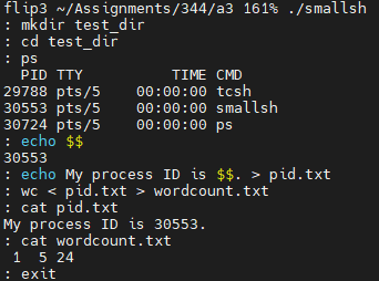
smallsh
This project was for my first operating system class. Other projects I did for this class include: a multithreaded producer-consumer pipeline, one time pad, and map reduce. Smallsh is a simple Linux shell. It has three built in commands: exit, cd, and status. Exit and cd are self-explanatory; status prints the exit or termination status of the most recent background task. The shell expands the variable "$$" to its own process ID. The shell supports input and output redirection as well as running tasks in foreground or background. The shell uses signal handlers to prevent SIGINT from terminating the shell or any background processes, instead only terminating the foreground task. The SIGSTP signal toggles foreground only mode, which forces all commands to run in foreground.